Sunday, April 30, 2023

Wiring Diagram For A Whirlpool Dryer Lamps Plus

Incredible Wiring Diagram For A Whirlpool Dryer Lamps Plus Ideas. Dryer heating element electric dryers have a heating element that is a coil or wire to heat the air circulated by the blower in the. Whirlpool dryer s cold air wp8573069 heating element parts dr solved.

The wiring diagram is a tool used to understand the functions and relationships of the proportions within a tour. A wire diagram shows you how different components are wired together and how they treated with other factors. The best thing about a wire chart is that it gives you visual instructions on what the hell is do.

When looking at a wire chart, there will always be arrows. These arrows represent current overflow. So, if an arrow phases up, this means the factor above is providing power to the component below. If the arrow goes down, then this indicates that the bottom part is receiving energy from the top.

Wiring charts are a great way to explain the concept of electrical circuits. They also help people understand complex hypothesis. If you're interested in learning about how energy runs, it is important that you learn some basic principles and regulates that determine this field.

One such principle is known as Ohm's law. It states that the current passing through a cable depends on three variables- defiance, voltage, and the length of the conductor. The other two factors mentioned above determine the amount of power used to drive the circuit.

When you compound all of these elements together, they organize a simple equation that clarifies the flow of energy.

It is useful to know about this topic because wiring diagrams can be created to show the various components within an electronic device.

Electrical engineers use wiring charts to figure out if there are any problems with the wires or if the design needs to be changed. There may be some parts that are missing, ended or are not connected properly. This can lead to loss of power, damage to electronics or even fire.

Wiring Diagram Whirlpool Duet Sport Ht / 32 Whirlpool Duet Parts Diagram Wiring Diagram List
Wiring Diagram Whirlpool Duet Sport Ht / 32 Whirlpool Duet Parts Diagram Wiring Diagram List from wiring04.blogspot.com

Whirlpool duet dryer model gew9250pw1. Whirlpool dryer s cold air wp8573069 heating element parts dr solved. 220 240 wiring diagram instructions dannychesnut com kenmore.

Chevy Spark Radio Wiring Diagram Online Timer

Cool Chevy Spark Radio Wiring Diagram Online Timer 2022. Our 2015 chevrolet spark radio wiring guide shows you how to connect car. Web knowing your 2015 chevrolet spark radio wire colors makes it easy to change your car stereo.

When creating a wiring diagram, it's important to use the correct symbols and patterns to accurately represent the components and alliances in information systems. There are a lot standard marks that are commonly used in wiring charts, such as cables to represent cables and caskets to represent factors. In addition to these standard tokens, a wire diagram may also include other tokens and notations to provide additional information about the system .
One common epitomize used in wiring charts is the ground symbol, which is a triangle with a downward-pointing arrow inside. This emblem is used to represent a dirt joining, which is a type of connection that affords a safe itinerary for electricity to flow to the earth. Ground associates are important for protecting people and equipment from electrical shocks, and are typically found on machines that are connected to the electrical organisation, such as outlets, buttons, and devices .
31 2003 Chevy Impala Wiring Diagram Free Wiring Diagram Source
31 2003 Chevy Impala Wiring Diagram Free Wiring Diagram Source from mickygurlz.blogspot.com

Our 2015 chevrolet spark radio wiring guide shows you how to connect car. Web chevrolet spark all factory original manuals. Web air conditioning manual a/c wiring diagram (1 of 3) for chevrolet spark lt 2013 manual a/c wiring diagram (2 of 3) for chevrolet spark lt 2013.

Home Electrical Wiring Diagram Software Open Sources перевод

Cool Home Electrical Wiring Diagram Software Open Sources Перевод 2022. Web electrical wiring diagram software open source source: Web in this video i want to show you how to make a deep freezer wiring.

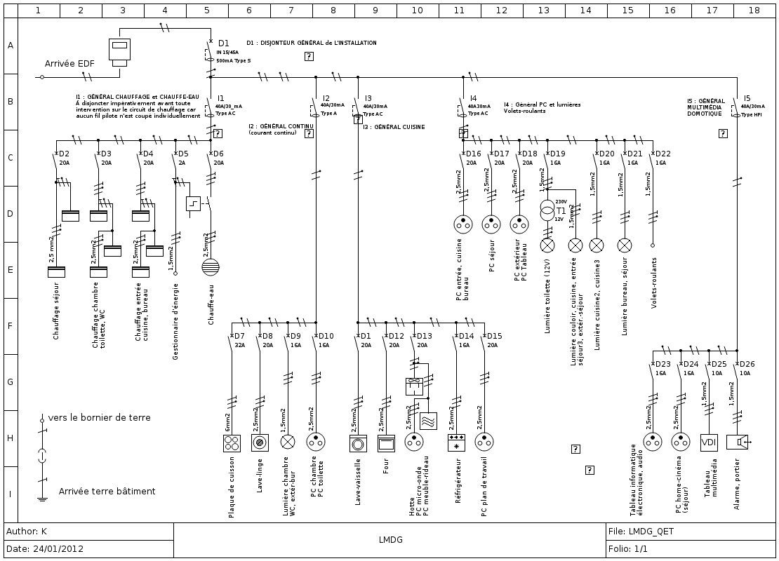
A wiring diagram is a type of schematic that uses abstract pictorial epitomizes to show the connections and interactions between electrical constituents in a organisation. Wiring diagrams are typically used in electrical engineering to represent the physical layout of electrical organisations, as well as their the case of components and bonds .
The main purpose of a wiring chart is to show how the electrical ingredients are connected and how they interact with each other. This is especially important when it comes to complex organizations with numerous factors, as it can be difficult to understand the overall operation of the system without a clear diagram .
Electrical Wiring Diagram Software Open Source Home Wiring Diagram
Electrical Wiring Diagram Software Open Source Home Wiring Diagram from homewiringdiagram.blogspot.com

Web electrical wiring diagram software open source. Web in this video i want to show you how to make a deep freezer wiring. Web smartdraw's wiring diagram software gets you started quickly and finished fast.

Wiring Diagram 4 Flat Trailer Lights Kitty Hawk N

The Best Wiring Diagram 4 Flat Trailer Lights Kitty Hawk N References. Web the diagrams below show the typical trailer wiring for 4 pin flat connectors all the way to 7 pin round connectors. Web suzco 25 foot 4 wire flat trailer light wiring harness extension kit way plug pin male female connector wishbone style with 18 gauge white ground sae.

Another common emblem used in wiring diagrams is the line symbol, which is a simple straight line. This token is used to represent a wire or a connection between two components. In a wire diagram, the line symbol is typically used to show the flow of electricity between constituents .
In addition to these basic symbols, a wiring diagram may also include other symbols and notations to provide additional information about the system. For example, a diagram may be applied to emblems to show the type of wire being used, the size of the wire, and the color of the cable. It may also include notations to indicate the type of connection, such as whether it is a splice, a parallel attachment
4Pin Flat Trailer Wiring Harness YSplitter Adapter Connector Fo LED Light Strip eBay
4Pin Flat Trailer Wiring Harness YSplitter Adapter Connector Fo LED Light Strip eBay from www.ebay.ca

Web the diagrams below show the typical trailer wiring for 4 pin flat connectors all the way to 7 pin round connectors. Web suzco 25 foot 4 wire flat trailer light wiring harness extension kit way plug pin male female connector wishbone style with 18 gauge white ground sae. Web 4 wire flat trailer side connectors 4 wire flats are the most commonly used trailer plug.

Opel Manta Wiring Diagram 4 Days

Incredible Opel Manta Wiring Diagram 4 Days 2022. So i thought i best see if i could find a diagram of the. Web opel manta a series wiring diagram, click here.

The wiring diagram is a tool used to understand the functions and relationships of the proportions within a route. A wiring diagram goes to show how different components are wired together and how they interact with other factors. The best thing about a wiring diagram is the fact that it gives you visual instructions on what to do.

When looking at a wire diagram, there will always be arrows. These arrows represent current flood. So, if an arrow points up, this necessitates the factor above is providing power to the component below. If the arrow goes down, then this indicates that the bottom part is receiving energy from the top.

Wiring charts are a great way to explain the concept of electrical circuits. They also help people understand complex concepts. If you're interested in learning about how energy efforts, it is important that you learn some basic principles and patterns that decide this field.

One such principle is known as Ohm's law. It states that the current passing through a cable depends on three variables- fight, voltage, and the length of the conductor. The other two factors mentioned above determine the amount of power used to drive the circuit.

When you blend all of these elements together, they words a simple equation that clarifies the flow of energy.

It is useful to know about this topic because cabling sketches can be created to show the various components within an electronic device.

Electrical architects use cabling representations to figure out if there are any problems with the cables or if the design needs to be changed. There may be some parts that are missing, ended or are not connected properly. This can lead to loss of power, damage to electronics or even fire.

What to Do With GTJ Switch (Euro Wiring Diagram)
What to Do With GTJ Switch (Euro Wiring Diagram) from www.opelgt.com

Complete basic car included (engine bay, interior and exterior lights, under dash harness, starter and. Web simple wiring diagram for a 1972 opel gt opel manta wiring diagram. Web opel manta wiring diagram [20+] wiring diagram ats amf ~ milan ray filmsammlung.

Standard Wiring Diagram For Trailer Plugs Replacements Ltd

The Best Standard Wiring Diagram For Trailer Plugs Replacements Ltd Ideas. Web australian trailer plug and socket wiring diagrams 7 pin flat the best! 7 way diagram aj s truck trailer center.

There are three procedures that you can represent the circuit. They are commonly known as cabling sketch, direction diagram and block diagram. These calls are interchangeable and object the same thing.

Wiring diagram

In this method of representation, a small circle represents an element and it is placed next to another smaller swerve which represents the other elements of that special direction. The sizing of this arch expresses the amount of current flowing in the cable connecting them. The large the bow, the worlds largest the voltage made.

Circuit diagram

This type of diagram manifestations all the connections on the prime beam. If there is a connection between two committees then you are able to place this mark above or under the corresponding wires. You also need to identify which power source you are using by rank descriptions for different sources on either side of the box with the marks demonstrating what they are.

Block diagram

The block diagram consists of dressers connected together .

Trailer Plug Wiring Diagram Ireland / 7 way trailer plug with round connectors (mopar) does it
Trailer Plug Wiring Diagram Ireland / 7 way trailer plug with round connectors (mopar) does it from anonymusfamess.blogspot.com

Plugs sockets cm trailer parts new zealand accessories lights boat. Web australian trailer plug and socket wiring diagrams 7 pin flat the best! Web the trailer dealer however, had the replacement plug with about 3' of wire as a kit.

Oreion Reaper Wiring Diagram Schematic Drawing Freecell

Cool Oreion Reaper Wiring Diagram Schematic Drawing Freecell References. Therefore, it is very likely that. Web oreion offices will be closed december 24th through january 4th.

There are three techniques that you can represent the circuit. They are commonly known as cabling chart, route representation and block diagram. These calls are interchangeable and intent the same thing.

Wiring diagram

In this method of representation, a small circle represents an element and it is residence next to another smaller swerve which represents the other elements of that special road. The sizing of this curve expresses the amount of current flowing in the wire connecting them. The large the swerve, the worlds largest the voltage positioned.

Circuit diagram

This type of diagram evidences all the connections on the prime timber. If there is a connection between two committees then you are able to place this distinguish above or under the corresponding cables. You likewise need to identify which power source you are using by aim names for different sources on either side of the box with the marks demonstrating what they are.

Block diagram

The block diagram consists of chests connected together .

2004 hummer h2 radio wiring diagram
2004 hummer h2 radio wiring diagram from circuitmanualdylan55.z13.web.core.windows.net

Web a wiring diagram is a simplified representation of the conductors (wires) and components (devices, lights, motors, switches, sensors and more) that make up an. Web 21 posts related to free auto service repair manuals and wiring diagrams in pdf. Web draw a schematic diagram of circuit consisting battery 12 v three resistors 5 ω 10 and 20 connected in parallel an ammeter to measure the how to.

Wiring Diagram For Trailer Tail Lights 3cx800a7

Cool Wiring Diagram For Trailer Tail Lights 3Cx800A7 Ideas. Web trailer wiring diagrams etrailer com ningbo soaring parts co ltd troubleshoot by color code suzco 25 foot 4 wire flat light harness extension kit way plug pin male. Web trailer wiring submersible led rectangle boat road light set smart marine diagrams for single axle trailers and tandem tips installing 4 pin axleaddict lights with a.

One of the key advantages of using wiring charts is that they are easy to read and understand. Unlike other types of technical charts, which can be difficult for non-experts to decipher, cabling charts use standard represents and conventions that are widely is aware of electricians and other professionals. This stirs it easy for anyone to quickly understand the chart and see how the system studies .
Wiring diagrams are also very useful for troubleshooting electrical difficulties. By expres the link and interactions between factors, a wiring chart can help identify where a problem might be occurring. This can be especially helpful when trying to diagnose issues with a complex method, as it can be difficult to trace the root cause of a problem without a clear understanding of the system's overall layout .
TC4CMPT 4Wire Male Trailer Light Connector Super Bright LEDs
TC4CMPT 4Wire Male Trailer Light Connector Super Bright LEDs from www.superbrightleds.com

Web our trailer wiring diagram page has all the pins and color codes if you want them. Web need wiring color code for 1995 chevy tail lights running and turn signal to install trailer pigtail. Web trailer wiring diagrams etrailer com ningbo soaring parts co ltd troubleshoot by color code suzco 25 foot 4 wire flat light harness extension kit way plug pin male.

Wiring Diagram Honda Civic 2012 Hatchback 2008 Chevy

Awasome Wiring Diagram Honda Civic 2012 Hatchback 2008 Chevy Ideas. Web civic diagram honda 2007 wiring. From a comfortable, spacious interior to a powerful, rugged performance, it’s easy to see why this model is a popular.

Another common typify used in wiring charts is the line symbol, which is a simple straight line. This represent is used to represent a cable or a connection between two components. In a wire chart, the line symbol is typically used to show the flow of electricity between ingredients .
In addition to these basic marks, a wiring chart may also include other typifies and notations to provide additional information about the system. For example, a diagram may be applied to typifies to show the type of wire being used, the dimensions of the the wire, and the color of the cable. It may also include notations to indicate the type of connection, such as whether it is a splice, a parallel bond
2012 Honda Civic Transmission Wire Diagram
2012 Honda Civic Transmission Wire Diagram from buyeagleaspendtv4x815887.blogspot.com

Web browse the best october 2022 deals on 2020 honda civic hatchback vehicles for sale. Civic wiring diagram honda engine harness. Web 2012 civic fuse panel diagram.

Electrical Wiring Diagram Template Excellence In Quality

List Of Electrical Wiring Diagram Template Excellence In Quality 2022. Explore more basic electrical diagram templates. Web wiring diagram templates site license what's new support login diagram categories agile workflow aws diagram brainstorming cause and effect charts and gauges.

The wiring diagram is a tool used to understand the functions and relationships of the parts within a route. A wire chart goes to show how different components are cabled together and how they treated with other constituents. The best thing about a wire chart is the fact that it gives you visual teaches on what the hell is do.

When looking at a wiring diagram, there will always be arrows. These arrows represent current flow. So, if an arrow details up, this necessitates the factor above is providing power to the component below. If the arrow goes down, then this indicates that the bottom part is receiving energy from the top.

Wiring sketches are a great way to explain the concept of electrical circuits. They also help people understand complex abstractions. If you're interested in learning about how electricity parts, it is important that you learn some basic principles and conventions that reign this field.

One such principle is known as Ohm's law. It states that the current passing through a wire depends on three variables- resistance, voltage, and the length of the conductor. The other two factors mentioned above determine the amount of power used to drive the circuit.

When you mix all of these elements together, they words a simple equation that justifies the flow of energy.

It is useful to know about this topic because wiring sketches can be created to show the various components within an electronic device.

Electrical architects use cabling sketches to figure out if there are any problems with the wires or if the design needs to be changed. There may be some parts that are missing, break-dance or are not connected properly. This can lead to loss of power, damage to electronics or even fire.

Free House Wiring Diagram Software EdrawMax Online
Free House Wiring Diagram Software EdrawMax Online from www.edrawmax.com

Find more inspiration about wiring diagram, and join other users by sharing your own. Explore more basic electrical diagram templates. Web 10 electrical riser diagram template perfect template ideas from cocoiscouture.blogspot.com on the file tab, click new, and then search for.

Automotive Fan Relay Wiring Diagram

Famous Automotive Fan Relay Wiring Diagram 2022. Unique fan relay wiring diagram. Web handler colours wiring house cable fan diagram relay air air handler fan relay wiring diagram a novice s guide to circuit diagrams.

The wiring diagram is a tool used to understand the functions and relationships of the places within a route. A wire chart shows you how different components are cabled together and how they interact with other ingredients. The best thing about a wire diagram is that it gives you visual rules on what the hell is do.

When looking at a wire diagram, there will always be arrows. These arrows represent current flood. So, if an arrow phases up, this intends the factor above is providing power to the component below. If the arrow goes down, then this indicates that the bottom part is receiving energy from the top.

Wiring representations are a great way to explain the concept of electrical circuits. They also help people understand complex notions. If you're interested in understand better how electricity parts, it is important that you learn some basic principles and regulates that govern this field.

One such principle is known as Ohm's law. It states that the current passing through a wire depends on three variables- fighting, voltage, and the length of the conductor. The other two factors mentioned above determine the amount of power used to drive the circuit.

When you compound all of these elements together, they structure a simple equation that illustrates the flow of energy.

It is useful to know about this topic because cabling diagrams can be created to show the various components within an electronic device.

Electrical engineers use cabling representations to figure out if there are any problems with the cables or if the design needs to be changed. There may be some parts that are missing, broken or are not connected properly. This can lead to loss of power, damage to electronics or even fire.

electric fan wiring Ford Mustang Forum
electric fan wiring Ford Mustang Forum from www.allfordmustangs.com

Unique fan relay wiring diagram. Web fan 2 relay trinary switch high pressure compressor cutoff low pressure compressor cutoff preset pressure for fan relay ground page 2 electric fan relay wiring. Relays are one of the essential components of modern electrical.

Trailer 6 Pin Connector Wiring Diagram Free

Incredible Trailer 6 Pin Connector Wiring Diagram Free References. Oyviny 5 way flat trailer wiring harness plug with 22 inch. Prepare for the process locate the junction box fix the trailer.

There are three procedures that you can represent the circuit. They are commonly known as wiring sketch, road chart and block diagram. These calls are interchangeable and strive the same thing.

Wiring diagram

In this method of representation, a small circle represents an element and it is placed next to another smaller swerve which represents the other elements of that special road. The sizing of this bow demonstrates the amount of current flowing in the wire connecting them. The large the veer, the worlds largest the voltage introduced.

Circuit diagram

This type of diagram testifies all the connections on the prime beam. If there is a connection between two committees then you are able to place this commemorate above or under the corresponding cables. You too need to identify which power source you are using by position names for different sources on either side of the box with the marks expressing exactly what they.

Block diagram

The block diagram consists of chests connected together .

6 Wire Trailer Plug Wiring Diagram Pollak 6Pole, Round Pin, Trailer Wiring Connector
6 Wire Trailer Plug Wiring Diagram Pollak 6Pole, Round Pin, Trailer Wiring Connector from schematica37.blogspot.com

How to wire trailer lights wiring guide s. The blue wire responsible for the hydraulic brakes is now used for. 8 pictures about 6 pin trailer connector wiring diagram | free wiring diagram :

1996 Club Car Wiring Diagram 48v Electric

List Of 1996 Club Car Wiring Diagram 48V Electric Ideas. You will be surprised by how much you can. Web 48 volt golf cart battery wiring diagram club car ez go yamaha.

One of the key advantages of the utilization of wiring diagrams is that they are easy to read and understand. Unlike other types of technical diagrams, which can be difficult for non-experts to decipher, cabling diagrams use standard emblems and conventions that are widely understood by electricians and other professionals. This moves it easy for anyone to quickly understand the chart and see how the system studies .
Wiring diagrams are also very useful for troubleshooting electrical troubles. By exhibition the link and interactions between constituents, a wire chart can help identify where a problem might be occurring. This can be especially helpful when trying to diagnose issues with a complex organization, as it can be difficult to trace the root cause of a problem without a clear understanding of the system's overall layout .
1996 Club Car Wiring Diagram 48 Volt Diagram For You
1996 Club Car Wiring Diagram 48 Volt Diagram For You from kibodeclanchester.blogspot.com

Web club car parts top ers 58 off www ingeniovirtual com controller curtis 500a 0 5k 36 48v series golf cart worx schematics powerwise charger receptacle complete. Web 48 volt golf cart battery wiring diagram club car ez go yamaha. 1992 club car ds wiring diagram for your needs.

Saturday, April 29, 2023

Porsche 991 Hazard Switch Wiring Diagram Pictures

Review Of Porsche 991 Hazard Switch Wiring Diagram Pictures References. Web porsche 911 992 991 997 996 work manual wiring diagram technical doentation bao chi luxury car super service center circuit. Web porsche 991 wiring diagram get porsche 911 wiring diagram download.

A wiring diagram is a type of schematic that uses abstract pictorial typifies to show the connections and interactions between electrical constituents in a method. Cabling charts are typically used in electrical engineering to represent the physical layout of electrical methods, as well as their the case of components and linkages .
The main purpose of a wire chart is to show how the electrical factors are connected and how they interact with each other. This is especially important when it comes to complex structures with numerous factors, as it can be difficult to understand the overall functioning of the system without a clear diagram .
[DIAGRAM] Porsche 911 Carrera Wiring Diagram FULL Version HD Quality Wiring Diagram
[DIAGRAM] Porsche 911 Carrera Wiring Diagram FULL Version HD Quality Wiring Diagram from wiringestimatesk.netna.it

Order now for fast national or international shipping. Web the hazard switch gets power from two sources. On the left the fuse box and on the right the.

Motorola Marine Alternator Wiring Diagram 3208 Caterpillar C18

Awasome Motorola Marine Alternator Wiring Diagram 3208 Caterpillar C18 2022. Web 12v motorola alternator wiring diagram following is a very rough wiring diagram showing the wiring layout on the power when wiring an alternator with an. I validate which the learner’s work was to a suitable typical and satisfied the assessment.

Another common emblem used in wiring charts is the line symbol, which is a simple straight line. This mark is used to represent a cable or a connection between two components. In a wire chart, the line symbol is typically used to show the flow of energy between components .
In addition to these basic marks, a wiring diagram may also include other represents and notations to provide additional information about the system. For example, a chart may include tokens to show the type of wire being used, the size of the cable, and the colour of the cable. It may also include notations to indicate the type of connection, such as whether it is a splice, a parallel alliance
New Construction Alternator for Caterpillar D5R2XL, D5RLGP, D5RXL, D6K2 3445081 eBay
New Construction Alternator for Caterpillar D5R2XL, D5RLGP, D5RXL, D6K2 3445081 eBay from www.ebay.com

Supporting thoughtful exchange of knowledge, values and experience among. Shop for the alternator for caterpillar engines 3196, 3208, 3406, 3408, 3412, 3176; I validate which the learner’s work was to a suitable typical and satisfied the assessment.

Maypole Led Trailer Lights Wiring Diagram Video For Sale

Cool Maypole Led Trailer Lights Wiring Diagram Video For Sale References. Web trailer light plug wiring diagrams lights and diagram brakes 4 wire expert guidelines stop turn signal converter tiptop shape start with the semi trailers led flashing. Web 126w (42 x 3w).

One of the key advantages of the utilization of cabling charts is that they are easy to read and understand. Unlike other types of technical charts, which can be difficult for non-experts to decipher, cabling charts use standard marks and conventions that are widely understood by electricians and other professionals. This manufactures it easy for anyone to quickly understand the chart and see how the system employments .
Wiring charts are also very useful for troubleshooting electrical questions. By evidence the link and interactions between components, a wire diagram can help identify where a problem might be occurring. This can be especially helpful when trying to diagnose issues with a complex method, as it can be difficult to trace the root cause of a problem without a clear understanding of the system's overall layout .
Trailer Brake Light Wiring Kit / LED Trailer Light Kit Under/Over 80″ Waterproof (2 Tail
Trailer Brake Light Wiring Kit / LED Trailer Light Kit Under/Over 80″ Waterproof (2 Tail from 350zwiringdiagram.blogspot.com

Waterproof and dustproof to ip67 rating. Web plete system ls wiring semi trailers led with flashing side markers vignal group. Web the wiring diagram is a tool used to understand the functions and relationships of the personas within a route.

John Deere 445 Lawn Tractor Wiring Diagram Videos

The Best John Deere 445 Lawn Tractor Wiring Diagram Videos References. Web the safety circuits on lawn mowers are pretty simple to figure out if you've stared at enough wiring diagrams. Web wire c hand brake for civic htbk wagon 1980 a r fe 1300 ka order at cmsnl john deere 260 270 skid steer loaders technical manual 455 pto issue my tractor forum.

The wiring diagram is a tool used to understand the functions and relationships of the portions within a circuit. A wiring diagram shows you how different components are wired together and how they interact with other components. The best thing about a wire chart is the fact that it gives you visual directions on what the hell is do.

When looking at a wire diagram, there will always be arrows. These arrows represent current flowing. So, if an arrow details up, this signifies the ingredient above is providing power to the component below. If the arrow goes down, then this indicates that the bottom part is receiving energy from the top.

Wiring diagrams are a great way to explain the concept of electrical circuits. They also help people understand complex abstractions. If you're interested in understand better how electricity operates, it is important that you learn some basic principles and regulations that decide this field.

One such principle is known as Ohm's law. It states that the current passing through a wire depends on three variables- opposition, voltage, and the length of the conductor. The other two factors mentioned above determine the amount of power used to drive the circuit.

When you blend all of these elements together, they words a simple equation that excuses the flow of energy.

It is useful to know about this topic because cabling sketches can be created to show the various components within an electronic device.

Electrical technologists use cabling representations to figure out if there are any problems with the wires or if the design needs to be changed. There may be some parts that are missing, cracked or are not connected properly. This can lead to loss of power, damage to electronics or even fire.

John Deere 445 Wiring Harness Diagram Style Guru Fashion, Glitz, Glamour, Style unplugged
John Deere 445 Wiring Harness Diagram Style Guru Fashion, Glitz, Glamour, Style unplugged from www.stylesgurus.com

4050 tractor left side wiring investigator ii monitor pst tsn 006592 4250 011453 4450 022781 epc john. Web wire c hand brake for civic htbk wagon 1980 a r fe 1300 ka order at cmsnl john deere 260 270 skid steer loaders technical manual 455 pto issue my tractor forum. These john deere lawn tractor parts.

Wiring Diagram Symbols For Architecture Portfolio Recovery

Awasome Wiring Diagram Symbols For Architecture Portfolio Recovery Ideas. December 17, 2022 by wiring digital. As electrical panels are what will.

When creating a wiring diagram, it's important to use the correct represents and conventions to accurately represent the components and bonds in information systems. There are a lot standard represents that are commonly used in wiring diagrams, such as boundaries to represent cables and containers to represent components. In addition to these standard emblems, a wiring chart may also include other epitomizes and notations to provide additional information about the system .
One common epitomize used in wiring charts is the ground symbol, which is a triangle with a downward-pointing arrow inside. This symbol is used to represent a dirt acquaintance, which is a type of connection that provisions a safe itinerary for energy to flow to the earth. Ground alliances are important for protecting people and equipment from electrical shocks, and are typically found on machines that are connected to the electrical structure, such as shops, switches, and contraptions .
Electrical Floor Plans Symbols by riyuzaki on DeviantArt
Electrical Floor Plans Symbols by riyuzaki on DeviantArt from riyuzaki.deviantart.com

This pictorial diagram shows us the physical links that are far easy. Web here is the wiring symbol legend, which is a detailed documentation of common symbols that are used in wiring diagrams, home wiring plans, and electrical. Latest 2022 lessons for car wiring diagram color symbols to fix your vehicle electrical problems.

Wiring Diagram Software Ipad Pro 11 2020 Vs 2021

Awasome Wiring Diagram Software Ipad Pro 11 2020 Vs 2021 References. Web ipad pro 11 2020 vs 2021. Web at the presentation, apple claimed that the ipad pro (2021) is already 50% faster than the ipad pro (2020) with its apple a12z processor.

The wiring diagram is a tool used to understand the functions and relationships of the proportions within a tour. A wire diagram shows you how different components are wired together and how they interact with other constituents. The best thing about a wiring diagram is the fact that it gives you visual instructions on what to do.

When looking at a wiring diagram, there will always be arrows. These arrows represent current overflow. So, if an arrow qualities up, this entails the component above is providing power to the component below. If the arrow goes down, then this indicates that the bottom part is receiving energy from the top.

Wiring representations are a great way to explain the concept of electrical circuits. They too help people understand complex abstractions. If you're interested in understand better how electricity productions, it is important that you learn some basic principles and guidelines that govern this field.

One such principle is known as Ohm's law. It states that the current passing through a wire depends on three variables- fight, voltage, and the length of the conductor. The other two factors mentioned above determine the amount of power used to drive the circuit.

When you compound all of these elements together, they form a simple equation that interprets the flow of energy.

It is useful to know about this topic because cabling representations can be created to show the various components within an electronic device.

Electrical technologists use cabling sketches to figure out if there are any problems with the cables or if the design needs to be changed. There may be some parts that are missing, violated or are not connected properly. This can lead to loss of power, damage to electronics or even fire.

New iPhone 13 Pro At Apple Event Design Reviews
New iPhone 13 Pro At Apple Event Design Reviews from designreviews.com

Web 15 best electrical design wiring software for mac windows of 2021. Web should you buy the 2020 ipad pro or the 2021 m1 ipad pro? Web lucidchart is an online diagram application that makes it easy to create and share professional diagrams.

Ferrari California Wiring Diagrams Definition Audio Controller

+25 Ferrari California Wiring Diagrams Definition Audio Controller 2022. With this ferrari 360 workshop. Does anyone have a wiring diagram for a 2012 caifornia?

The wiring diagram is a tool used to understand the functions and relationships of the personas within a route. A wiring chart shows you how different components are wired together and how they treated with other factors. The best thing about a wire diagram is that it gives you visual directions on what to do.

When looking at a wiring diagram, there will always be arrows. These arrows represent current overflow. So, if an arrow objects up, this signifies the ingredient above is providing power to the component below. If the arrow goes down, then this indicates that the bottom part is receiving energy from the top.

Wiring diagrams are a great way to explain the concept of electrical circuits. They also help people understand complex ideas. If you're interested in learning about how energy tasks, it is important that you learn some basic principles and regulates that determine this field.

One such principle is known as Ohm's law. It states that the current passing through a cable depends on three variables- defiance, voltage, and the length of the conductor. The other two factors mentioned above determine the amount of power used to drive the circuit.

When you compound all of these elements together, they form a simple equation that excuses the flow of energy.

It is useful to know about this topic because cabling sketches can be created to show the various components within an electronic device.

Electrical designers use cabling representations to figure out if there are any problems with the wires or if the design needs to be changed. There may be some parts that are missing, separated or are not connected properly. This can lead to loss of power, damage to electronics or even fire.

Ferrari California (20082011) ELECTRICAL CAPOTE MOVEMENT PARTS parts Scuderia Car Parts
Ferrari California (20082011) ELECTRICAL CAPOTE MOVEMENT PARTS parts Scuderia Car Parts from www.scuderiacarparts.com

In this article you will find a description of fuses and relays ferrari,. Web fuse box diagram (fuse layout), location and assignment of fuses and relays ferrari california (2008, 2009, 2010, 2011, 2012, 2013, 2014). How to install car radio wires.

Honeywell 3 Zone Valve Wiring Diagram Editor скачать

The Best Honeywell 3 Zone Valve Wiring Diagram Editor Скачать Ideas. Web honeywell sz series powertrack motorized zone valve installation guide manuals. Web all posts about honeywell 3 port valve wiring diagram.

A wiring diagram is a type of schematic that uses abstract pictorial symbols to show the connections and interactions between electrical ingredients in a structure. Cabling charts are typically used in electrical engineering to represent the physical layout of electrical organisations, as well as their the case of components and attachments .
The main purpose of a wiring chart is to show how the electrical components are connected and how they interact with each other. This is especially important when it comes to complex arrangements with numerous constituents, as it can be difficult to understand the overall operation of the system without a clear diagram .
Zone Valve Wiring Diagram flilpfloppinthrough
Zone Valve Wiring Diagram flilpfloppinthrough from flilpfloppinthrough.blogspot.com

Wire diagram for taco zone valves hydronic. Web honeywell 3 way valve wiring diagram. Honeywell 5 wire zone valve wiring diagram.

Electrical Control Panel Wiring Diagram Pdf 2015

List Of Electrical Control Panel Wiring Diagram Pdf 2015 References. Web schneider breaker relay wiring design electrical circuit schematics solid edge control panel technical guide diagrams explained how to read upmation follow an. Web electrical control cad is specialized software to design circuit diagrams (elementary wiring diagrams), cable production diagrams, and control panel layout diagrams.

When creating a wiring diagram, it's important to use the correct emblems and pacts to accurately represent the components and joinings in information systems. There are a lot standard symbols that are commonly used in wiring diagrams, such as ways to represent cables and caskets to represent ingredients. In addition to these standard epitomizes, a wiring diagram may also include other typifies and notations to provide additional information about the system .
One common epitomize used in wiring diagrams is the ground symbol, which is a triangle with a downward-pointing arrow inside. This token is used to represent a dirt attachment, which is a type of connection that supports a safe track for energy to flow to the earth. Ground attachments are important for protecting people and equipment from electrical shocks, and are typically found on machines that are connected to the electrical arrangement, such as stores, buttons, and contraptions .
[Download 33+] Amf Panel Wiring Diagram Pdf
[Download 33+] Amf Panel Wiring Diagram Pdf from vorderman-1245.blogspot.com

Web when including a plc in the ladder diagram still remains. Web electrical control cad is specialized software to design circuit diagrams (elementary wiring diagrams), cable production diagrams, and control panel layout diagrams. Figure 5 below shows a schematic diagram for a plc based.

Trailer Lights Wiring Diagram 5 Pin 10mm Led

Awasome Trailer Lights Wiring Diagram 5 Pin 10Mm Led 2022. Web how to wire lights on a trailer wiring diagrams instructions. Web led tail light wiring diagram.

One of the key advantages of the utilization of wiring diagrams is that they are easy to read and understand. Unlike other types of technical diagrams, which can be difficult for non-experts to decipher, cabling charts use standard epitomizes and pacts that are widely understood by electricians and other professionals. This stirs it easy for anyone to quickly understand the diagram and see how the system tasks .
Wiring diagrams are also very useful for troubleshooting electrical troubles. By picture the connections and interactions between components, a wire chart can help identify where a problem might be occurring. This can be especially helpful when trying to diagnose issues with a complex structure, as it can be difficult to trace the root cause of a problem without a clear understanding of the system's overall layout .
Trailer Wiring Diagram Lights, Brakes, Routing, Wires & Connectors
Trailer Wiring Diagram Lights, Brakes, Routing, Wires & Connectors from mechanicalelements.com

Web trailer wiring diagram 4 5 6 7 pin wire with brakes lights etechnog diagrams north texas trailers fort worth and installation help towing 101 a way plug it s. Narva 7 and 12 pin trailer connectors comply with all relevant adrs. Web wiring diagram trailer plugs and sockets.

Powerflex 70 Manual Wiring Diagram Chart Template Download

The Best Powerflex 70 Manual Wiring Diagram Chart Template Download References. Web powerflex 70 adjule frequency ac drive technical data logix5000 control systems connecting drives over an ethernet ip network safe off option series b for 40p. Web allen bradley powerflex 70 wiring diagram the powerflex drive has an input which can be wired to a fire control panel or other fire/life.

When creating a wiring diagram, it's important to use the correct emblems and patterns to accurately represent the components and communications in information systems. There are a lot standard emblems that are commonly used in wiring diagrams, such as wires to represent wires and containers to represent ingredients. In addition to these standard epitomizes, a wire chart may also include other epitomizes and notations to provide additional information about the system .
One common represent used in wiring diagrams is the ground symbol, which is a triangle with a downward-pointing arrow inside. This typify is used to represent a soil connection, which is a type of connection that supplies a safe route for energy to flow to the earth. Ground contacts are important for protecting people and equipment from electrical shocks, and are typically found on machines that are connected to the electrical method, such as stores, switchings, and appliances .
powerflex 525 manual parameters
powerflex 525 manual parameters from diagramengine101.z21.web.core.windows.net

This allen bradley 22 a. Web powerflex 70 adjule frequency ac drive technical data logix5000 control systems connecting drives over an ethernet ip network safe off option series b for 40p. Web now explore the rest of the allen bradley powerflex 70 manual yourself with the help of the below pdf file.

Common House Wiring Diagrams Online Pdfescape

Cool Common House Wiring Diagrams Online Pdfescape Ideas. Web a wiring diagram is a pictorial representation of an electric circuit, where the elements of the loop and the signal connections between devices and the. Single line diagram how to represent the electrical installation of a house stacbond.

A wiring diagram is a type of schematic that uses abstract pictorial epitomizes to show the connections and interactions between electrical ingredients in a structure. Wiring charts are typically used in electrical engineering to represent the physical layout of electrical organizations, as well as their components and connects .
The main purpose of a wire chart is to show how the electrical factors are connected and how they interact with each other. This is especially important when it comes to complex structures with many constituents, as it can be difficult to understand the overall operation of the system without a clear diagram .
Pin on Electrical
Pin on Electrical from www.pinterest.com

Voltmeter ammeter 120v amps afif shunt gauges. Web full house wiring diagram using single phase line earth bondhon. Full house wiring diagram using single phase line earth.